Radxa Zero 3W
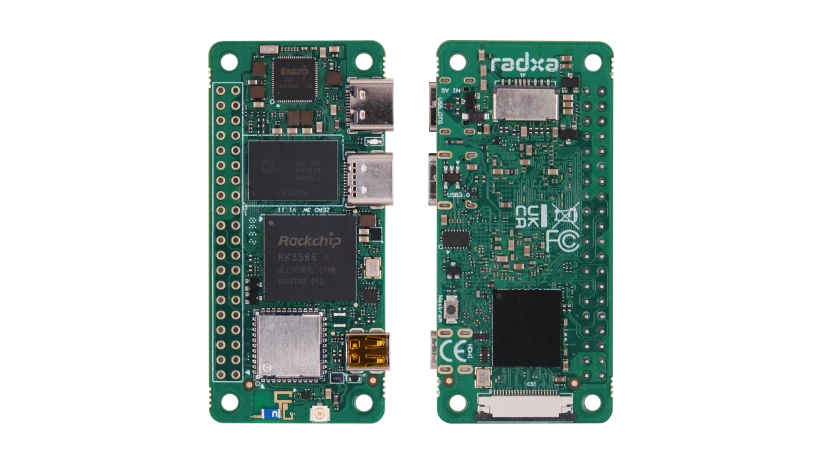
Radxa Zero 3W is a compact single-board computer (SBC) in the Raspberry Pi Zero form factor, built on the quad-core Rockchip RK3566. In the OpenIPC FPV world it has become one of the most popular bases for a ground station (VRX): its small size, onboard Wi-Fi, micro-HDMI video output and compatibility with the OpenIPC GS image make it an almost ideal receiver "brain".
Unlike a simple USB dongle, the Radxa Zero 3W is a full Linux computer: it receives the Wi-Fi stream from the drone, decodes video in hardware and outputs it to a screen or FPV goggles with low latency.
Specifications
| Parameter | Value |
|---|---|
| SoC | Rockchip RK3566, 4× ARM Cortex-A55 up to 1.6 GHz |
| GPU | Mali-G52 2EE (OpenGL ES 3.2, Vulkan 1.1) |
| NPU | 0.8 TOPS |
| RAM | LPDDR4, 1 / 2 / 4 / 8 GB (depending on version) |
| Storage | microSD + optional eMMC (0–64 GB) |
| Wireless | Wi-Fi 802.11 b/g/n (2.4 GHz) + Bluetooth 5.0, antenna connector |
| Video output | micro HDMI, up to 1080p@60 |
| USB | USB 2.0 Type-C (power / OTG) + USB 3.0 Type-C (host) |
| Expansion | 40-pin GPIO (Raspberry Pi compatible) |
| Power | USB-C, 5V / 2A |
| Dimensions | 65 × 30 mm (Pi Zero form factor) |
| OS | Debian, Ubuntu, Android, OpenIPC GS image |
Why the Radxa Zero 3W for a ground station
- Small size and weight — pocketable, easy to embed into a portable station or goggles.
- Hardware H.265/H.264 decoding on the RK3566 — low latency even at 1080p.
- Micro-HDMI — direct monitor or goggle connection, no USB adapters needed.
- 40-pin GPIO like the Raspberry Pi — works with the OpenIPC Bonnet expansion board, buttons, displays and joysticks.
- Ready-made OpenIPC GS image — nothing to compile, just flash it to a microSD.
- Low power draw — runs from a power bank in the field.
3W or 3E?
Zero 3W has Wi-Fi and Bluetooth (for wireless scenarios). Zero 3E has wired Ethernet instead of Wi-Fi. For an FPV ground station with an RTL8812 USB adapter, choose the 3W.
40-pin GPIO pinout
The Radxa Zero 3W has a 40-pin header that is Raspberry Pi compatible. Numbering and power rails are standard; the signal functions are provided by the RK3566.
| Pin | Signal | Pin | Signal | |
|---|---|---|---|---|
| 1 | 3.3V | 2 | 5V | |
| 3 | I2C SDA | 4 | 5V | |
| 5 | I2C SCL | 6 | GND | |
| 7 | GPIO | 8 | UART TX | |
| 9 | GND | 10 | UART RX | |
| 11 | GPIO | 12 | I2S / PCM | |
| 13 | GPIO | 14 | GND | |
| 15 | GPIO | 16 | GPIO | |
| 17 | 3.3V | 18 | GPIO | |
| 19 | SPI MOSI | 20 | GND | |
| 21 | SPI MISO | 22 | GPIO | |
| 23 | SPI SCLK | 24 | SPI CE0 | |
| 25 | GND | 26 | SPI CE1 | |
| 27 | USB2 D− * | 28 | USB2 D+ * | |
| 29 | GPIO | 30 | GND | |
| 31 | GPIO | 32 | PWM | |
| 33 | PWM | 34 | GND | |
| 35 | I2S | 36 | GPIO | |
| 37 | GPIO | 38 | I2S | |
| 39 | GND | 40 | I2S |
Notes
* On the Radxa Zero 3W, pins 27/28 are routed as an extra USB 2.0 host (USB2_HOST2_D−/D+). For the exact alternate function of each pin, see the official Radxa schematic.
How to build a ground station
What you need:
- Radxa Zero 3W (2 GB RAM or more recommended)
- microSD card (16 GB+) with the OpenIPC GS image
- RTL8812AU / RTL8812EU Wi-Fi adapter (network cards)
- A display via micro-HDMI or FPV goggles
- USB-C power (5V / 2A); a power bank in the field
- (Optional) OpenIPC Bonnet — combines 2S–6S power, a USB hub, 2× Wi-Fi, a joystick and an IMU on one board
For a step-by-step build, see the DIY Radxa GS Build guide.
First steps
- Flash the OpenIPC GS image onto a microSD card (e.g. with Raspberry Pi Imager or balenaEtcher).
- Connect the Wi-Fi adapter to a USB port (for range, use a powered USB hub or the Bonnet).
- Connect a display via micro-HDMI.
- Power the board over USB-C (5V / 2A).
- Configure the channel and link settings per the VRX Setup guide.
Power
Use a solid 5V/2A source. A weak power bank causes freezes and video loss under load.